Receiver Hardware
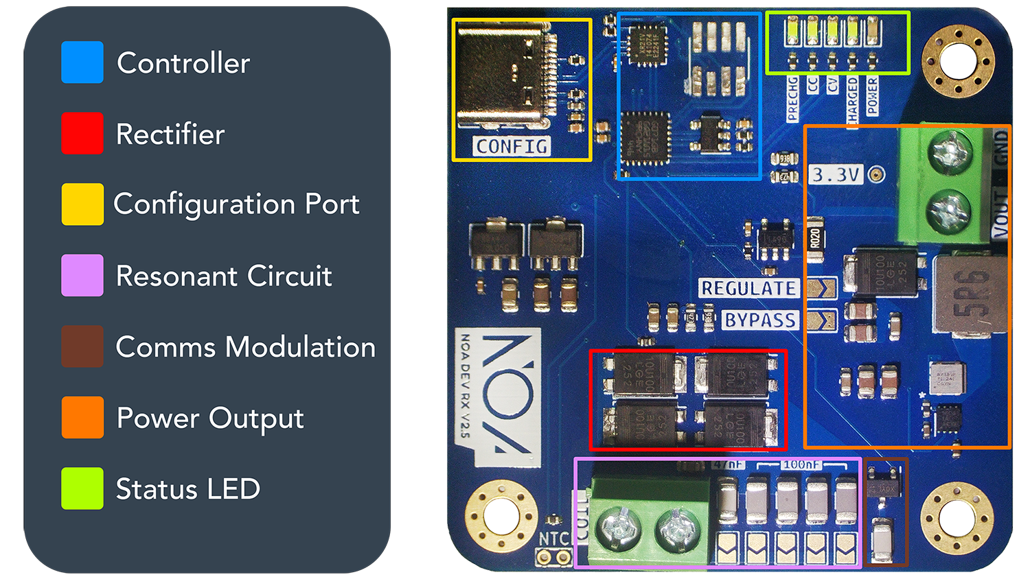
🟦 Controller
The microcontroller is in charge of both controlling and monitoring the flow of power and data through the receiver, as well as handling errors and enforcing protections. Our custom firmware lives here and is what enables our high efficiency, flexibility and ease of integration.
🟥 Rectifier
A basic full bridge diode rectifier turns the AC power that comes through the resonant circuit to DC.
🟨 Configuration Port
The USB-C configuration port enables you to configure the operating parameters of the receiver by connecting to a computer and using our web configuration tool.
🟪 Resonant Circuit
Together, the coil and capacitors form the resonant circuit which defines how the receiver resonates with the transmitted electromagnetic field. Perfect resonance is usually not the preferred setup as it can cause large voltage spikes that can cause issues. The formula for calculating your resonant frequency is: , where L is the coil inductance value and C is the resonant capacitor selected value.
Coil
The coil acts as the antenna for wireless power receiving. Three coil sizes have been included in your kit so you can choose the size most suitable to your application. Connect to the board using the screw terminal highlighted above.
Resonant Capacitors
The five resonant capacitors are connected in parallel using solder jumpers, so bridging multiple solder jumpers results in the capacitor values adding up. The larger gray capacitors have a value of 100nF each, and the small white capacitor is 47nF.
🟫 Communications Modulation
An additional (non-selectable) resonant capacitor is connected to the controller through a mosfet, which is used for modulating the power signal by changing the receivers resonant frequency. The transmitter is able to decode the modulated power signal through its current sense to perform receiver -> transmitter communications.
🟧 Power Output
Power is output through the screw terminal highlighted above. When the Bypass solder jumper is bridged, this will directly output the rectified voltage, so may require additional regulation afterwards depending on your requirements. When the Regulate solder jumper is bridged the power output comes from the integrated regulator which you may choose to output a fixed voltage or current using the configurator.
🟩 LEDs
The four status LEDs are used to indicate the current mode of operation. The modes are outlined in detail in Modes of Operation